Effects of Electric Current
Science Part 1 • Class 10th
In this chapter
- Energy transfer in an electric circuit
- Heating effects of electric current
- Magnetic effects of electric current
- Electric motor
- Electromagnetic induction
- Alternating current and direct current
- Electric generator
Learn the definitions, rules, diagrams, formulae and applications together.
Energy Transfer in an Electric Circuit
- A cell is the source of energy in an electric circuit.
- If a charge Q flows from A to B through a potential difference VAB, work is done on the charge.
- The energy given by the cell is transferred to the resistance.
- The resistor converts this energy into heat energy and its temperature increases.
The unit of electrical power is watt (W).
Heating Effect of Electric Current
When a resistor is connected in an electrical circuit, heat is produced in it due to the current. This is known as the heating effect of current.
Other useful forms:
H = I²Rt is called Joule's law of heating.
Uses of Heating Effect
- Water boiler
- Electric cooker
- Electric heater
- Electric iron
- Electric bulb
- Toaster
An alloy such as Nichrome is used as the heating element in an electric heater and cooker because electrical conductors having higher resistivity are used there.
Tungsten wire is used in an electric bulb. Because of current it gets heated to nearly 3400°C and emits light.
Electrical Energy, Fuse & MCB
When 1 kWh electrical energy is used, it is termed as 1 unit of energy.
Short circuit
- If live and neutral wires come in contact, a large current flows.
- Large heat is produced and inflammable material may catch fire.
Fuse and MCB
- A fuse wire melts when high current flows and breaks the circuit.
- An MCB opens the switch when current suddenly increases.
Magnetic Effect of Electric Current
A magnetic field is produced around a straight current-carrying conductor.
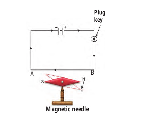
- When current flows through the wire, the magnetic needle turns.
- Reversing the current changes the direction of the needle.
- This shows that electricity and magnetism are closely related.
Magnetic Field Around a Conductor
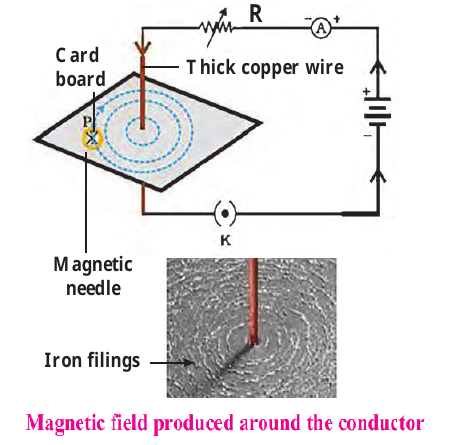
- Iron filings arrange themselves along the magnetic lines of force.
- The magnetic field reduces as distance from the wire increases, if current is unchanged.
- If current through the wire is increased, the intensity of magnetic field increases.
Right Hand Thumb Rule
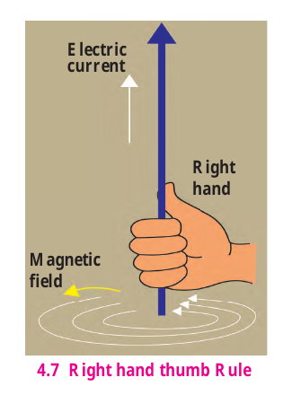
Hold the conductor in your right hand with the thumb pointing in the direction of current. The curled fingers show the direction of magnetic lines of force.
Thumb → Current Fingers → Magnetic field
Magnetic Field of a Loop and Solenoid
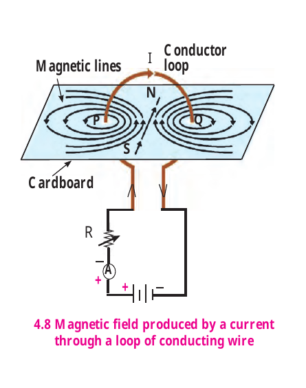
If there are n turns in the loop, the magnetic field is n times that produced by a single loop.
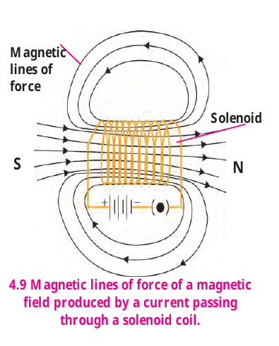
- A solenoid is a copper wire wound in a chain of loops like a spring.
- One end acts as North pole and the other as South pole.
- The magnetic field inside the solenoid is uniform.
Force on a Current-Carrying Conductor
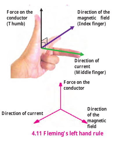
- When current flows through a conductor in a magnetic field, a force is exerted on the conductor.
- The force is perpendicular to both the magnetic field and the direction of current.
- If the current direction is reversed, the force direction is also reversed.
- The force is maximum when current is perpendicular to the magnetic field.
Index finger → magnetic field; middle finger → current; thumb → force on the conductor.
Electric Motor
A device changing electrical energy into mechanical energy is known as an electric motor.
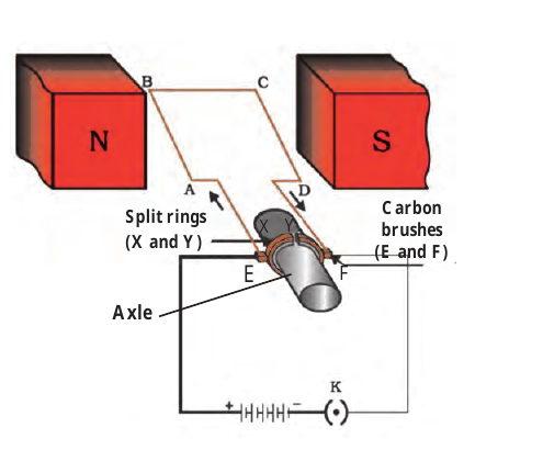
Construction
- Rectangular copper wire loop
- Magnet
- Split ring
- Carbon brushes
- Axle
Working
Forces act on opposite branches of the current-carrying coil. After every half rotation, the split ring reverses the current direction, so the loop continues rotating in the same direction.
Electromagnetic Induction
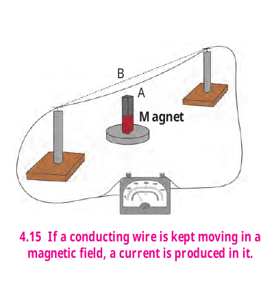
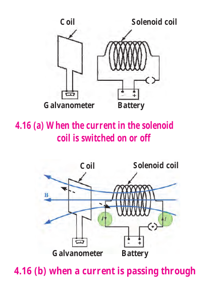
The generation of a current in a coil due to relative motion between the coil and the magnet is called electromagnetic induction.
Michael Faraday showed in 1831 that an electric current can be produced in a conductor with the help of a moving magnet.
Faraday's Law of Induction
Whenever the number of magnetic lines of force passing through the coil changes, current is induced in the coil. This is known as Faraday's law of induction.
- If current in the solenoid coil is switched on or off, current is induced in the coil.
- If current in the solenoid is increased or decreased, current is induced.
- Faster displacement gives larger galvanometer deflection.
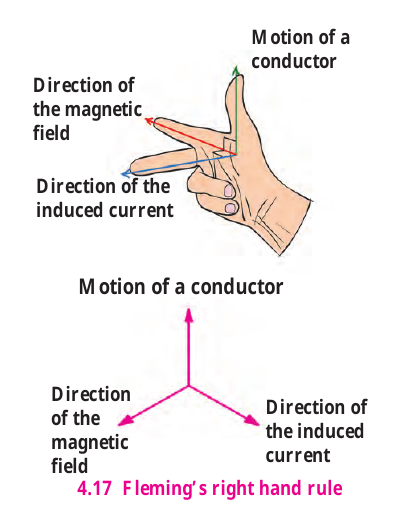
Thumb → motion of conductor; index finger → magnetic field; middle finger → induced current.
Galvanometer
Galvanometer is a sensitive device used for electrical measurements. Its pointer deflects on either side of zero depending on the direction of current.
- A small current through its coil produces a proportional rotation.
- Voltmeter and ammeter also work on the same principle.
Movement of a conductor or magnet relative to a magnetic field can produce an induced current.
Alternating Current and Direct Current
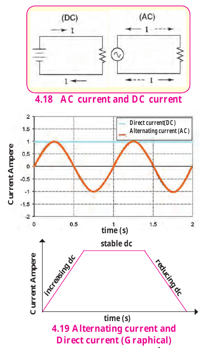
A non-oscillatory current flowing in one direction is called direct current.
A current changing in magnitude and direction after equal intervals of time is called alternating current.
The frequency of AC in India is 50 Hz (50 cycles per second). Home supply is AC.
AC and DC — Difference
| DC | AC |
|---|---|
| Flows in one direction. | Changes magnitude and direction periodically. |
| Non-oscillatory. | Oscillatory. |
| Does not reverse direction. | Reverses direction periodically. |
| Can be represented by increasing, stable or reducing DC. | Oscillation is sinusoidal with time. |
| — | India: 50 Hz. |
Explain the difference between AC and DC.
Electric Generator
An electric generator uses electromagnetic induction. Mechanical energy is used to rotate a coil in a magnetic field to produce electricity.
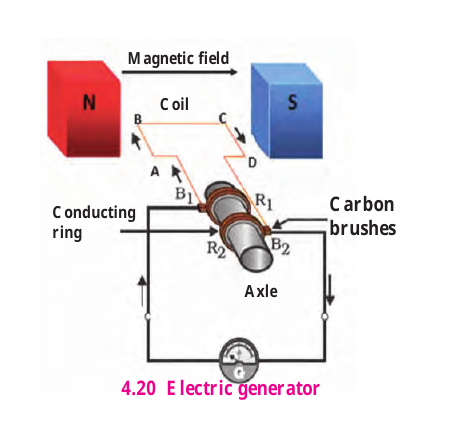
AC Generator
- A coil is rotated between the poles of a magnet.
- Induced current is produced in the coil.
- After every half rotation the direction of induced current reverses.
- Alternating current is produced in the external circuit.
How is DC obtained?
- In a DC generator, a split ring is fixed on the axle.
- The arrangement keeps the upward-going branch connected to one brush and the downward-going branch to the other brush.
- Hence the current flows in one direction in the external circuit.
A generator using this arrangement is called a DC generator.
| AC Generator | DC Generator |
|---|---|
| Conducting rings | Split ring |
| Produces AC | Produces DC |
| Direction changes in external circuit | Direction remains the same in external circuit |
Chapter 4 — Must Remember
- Heating effect: Heat is produced in a resistor due to current.
- Joule's law: H = I²Rt.
- Right hand thumb rule: Thumb → current; fingers → magnetic field.
- Fleming left hand: Index → field; middle → current; thumb → force.
- Electric motor: Electrical energy → mechanical energy.
- Electromagnetic induction: Change in magnetic lines through a coil induces current.
- Fleming right hand: Thumb → motion; index → field; middle → induced current.
- AC: Periodically changes magnitude and direction; India = 50 Hz.
- Generator: Mechanical energy → electrical energy.
Important Questions
- Explain Joule's law of heating.
- Explain short circuit and overloading.
- State the right hand thumb rule.
- Explain the magnetic field produced by a solenoid.
- State Fleming's left hand rule.
- Explain construction and working of an electric motor.
- Define electromagnetic induction and state Faraday's law.
- State Fleming's right hand rule.
- Differentiate between AC and DC.
- Explain construction and working of an AC generator.
- Explain how DC is obtained from a generator.
- Solve numerical problems using P = VI, P = I²R, P = V²/R and H = I²Rt.
For board answers, draw neat labelled diagrams for motor, generator, solenoid and Fleming's rules wherever required.